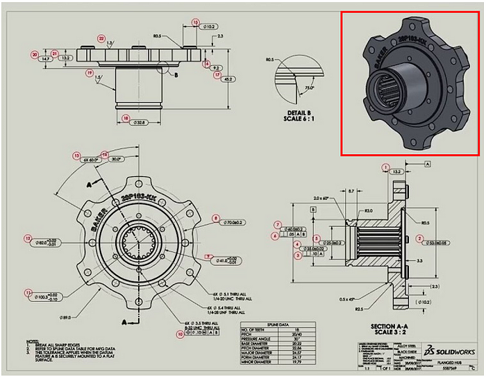
Here is an article written by our engineering team that will guide you on how to make the most out of your drafting experience. We hope to give you a succinct, yet complete depiction of the steps required to create a technical drawing, which is an especially broad topic.
Technical drawings are required to be submitted along with the CAD files if the parts contain:
It is not possible to indicate these requirements accurately through the CAD model alone.
In practice, it is generally better to include technical drawings with 3D CAD file submissions for CNC manufacturing, even if it does not contain any of the above-mentioned features. The 3D CAD files are used to program the CNC machine while the drawings are used as a visual reference by the operator. In fact, CNC manufacturers can machine and fabricate parts using the technical drawings alone with a large number actually preferring them over 3D CAD models. The main reasons for this are:
There are many different standards and practices used for drafting a technical drawing. The technique used does not matter as long as all the important technical requirements are indicated clearly.
A typical technical drawing consists of the following different components:

The title block, as shown by the red box in the sample drawing above, is an essential part of every technical drawing which contains basic information about the part, including its name, material, finishing, scale, dimensioning and tolerancing standards as well as information about the part’s designer and/or company. The title block helps manufacturers understand the utility and function of the part presented, allowing them to better comprehend the required specifications.
